PB-Access Kit Installation Guide
This guide will help you easily install and configure your PB-Access Kit for residential, business, or industrial applications.
Need support?
- Phone: (661) 294-3707 Ext. 2 (M-F 8:00 AM – 4:30 PM PST)
- Email: pacblu@paclock.com
Package Contents
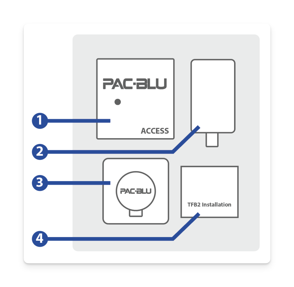
The PB-Access Kit includes the following:
1. PB-Access
- Mounting Screws & Anchors
2. Power Supply
3. TFB2
- Mounting Screws & Anchors
- Mounting Plate
- 2.5mm Allen Wrench
4. TFB2 Installation Guide
Before You Start
Tools You’ll Need (Not Included)
- Phillips and Flathead Screwdrivers
- Wire Cutters/Wire Strippers
- Drill (optional for mounting)
- Recommended drill bit for Drywall Anchors: 1/4″
Other Required Items
- Endpoint (e.g., Electric Strike, Maglock, Solenoid, etc.)
- Smartphone with Internet Connection
- PAC-BLU NexGen Mobile App
- Sentinel Installer Access (ask your account administrator for access)
Electrical Requirements and Safety Precautions
- Power Supply: The PB-Access Kit requires a 4-12V DC power supply. Use the included adapter for optimal compatibility.
- Warning: Always turn off power before installation to avoid shock or damage. Follow all local electrical codes.
- Prop 65 Notice: The kit contains materials subject to Prop 65 warnings for lead. Dispose of electronic waste properly.
Installing the Access Kit
Mounting the Access
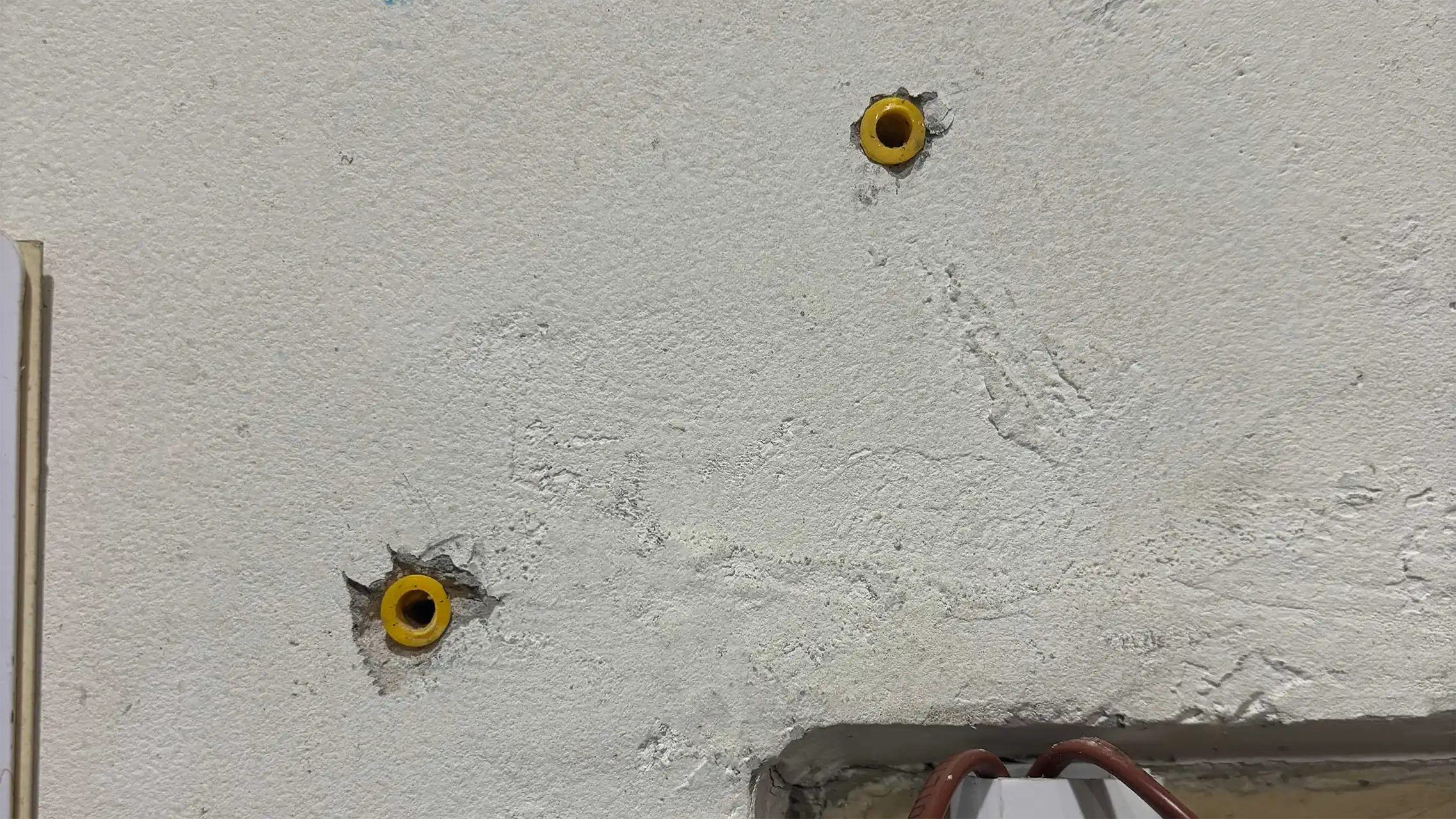
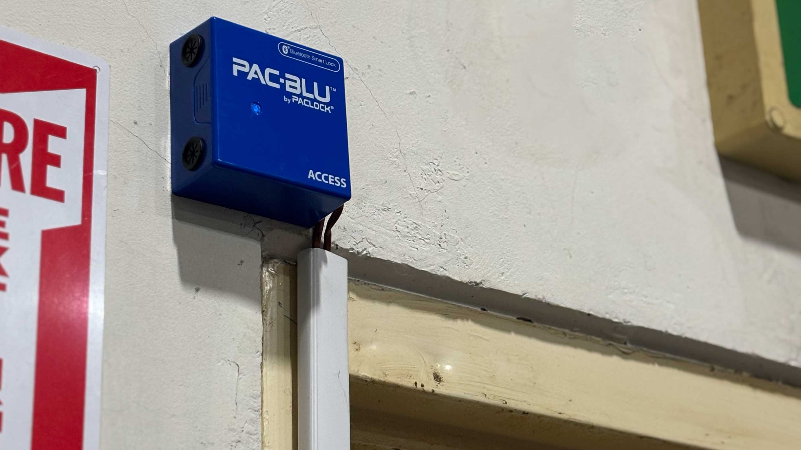
- Mount the PB-Access near the door, gate, or access point you want to secure.
- Ensure the area is free from excess moisture and direct sunlight.
- Use the provided screws and anchors to securely mount the unit.
Wiring the Access
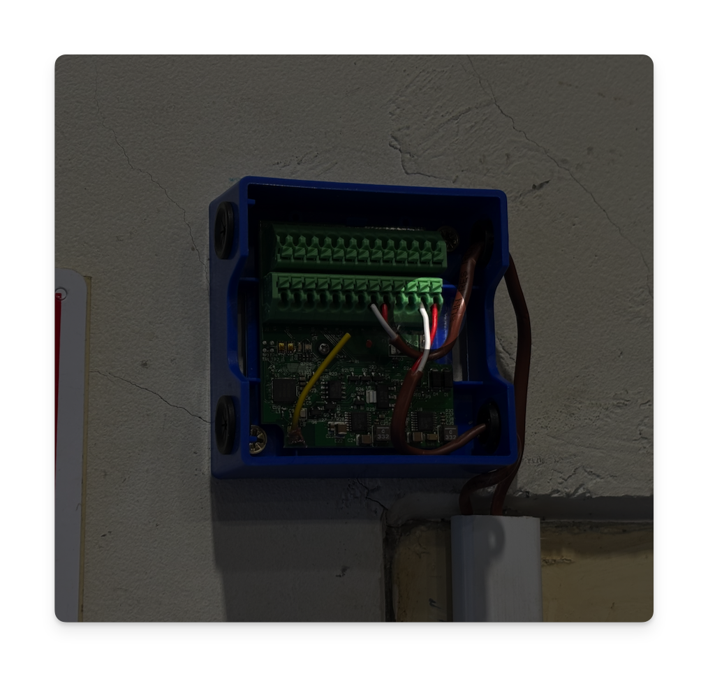
- Connect your endpoint (e.g., solenoid or DC motor) to the designated pins.
- Solenoid: Pins 5 and 6
- DC Motor: Pins 7 and 8
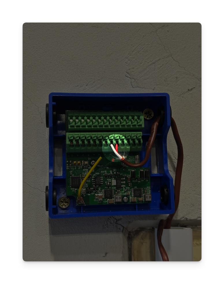
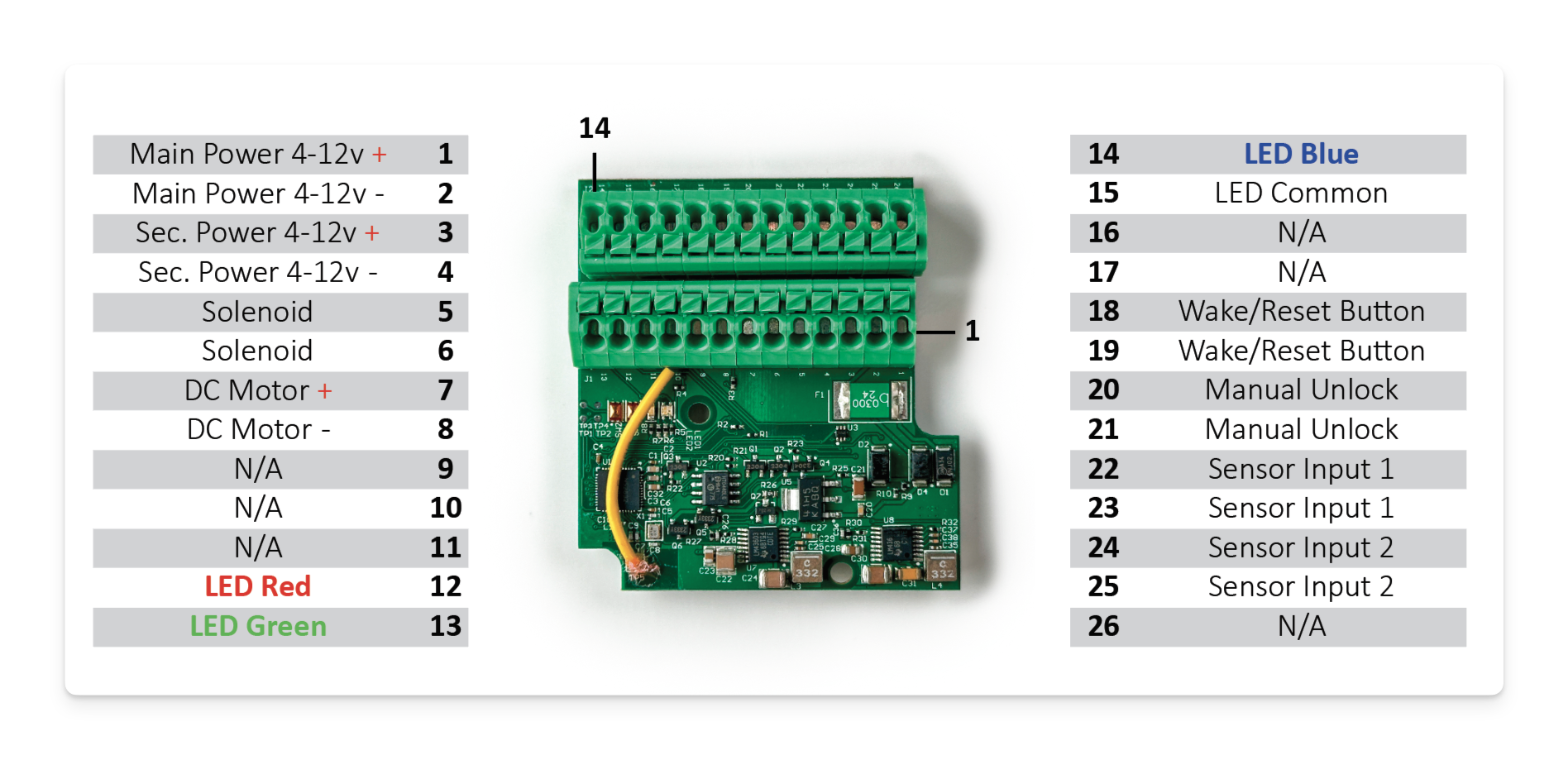
- Connect peripherals to their respective pins. Follow the wiring diagram below:
- Main Power (4-12V): Pins 1 (+) and 2 (-)
- Secondary Power (4-12V): Pins 3 (+) and 4 (-)
Wiring Diagram
- Main Power (4-12V): Pins 1 (+) and 2 (-)
- Secondary Power (4-12V): Pins 3 (+) and 4 (-)
- Solenoid: Pins 5 and 6
- DC Motor: Pins 7 and 8
- LEDs: Pins 12 (Red), 13 (Green), 14 (Blue), 15 (Common)
- Sensors: Pins 22 and 23 (Sensor Input 1), Pins 24 and 25 (Sensor Input 2)
Powering Up and Connecting
Powering Up
- After wiring, power up the device using the primary or secondary power input.
- Once powered, the LED will blink red and blue, indicating it’s ready to connect.
Connecting to the Access
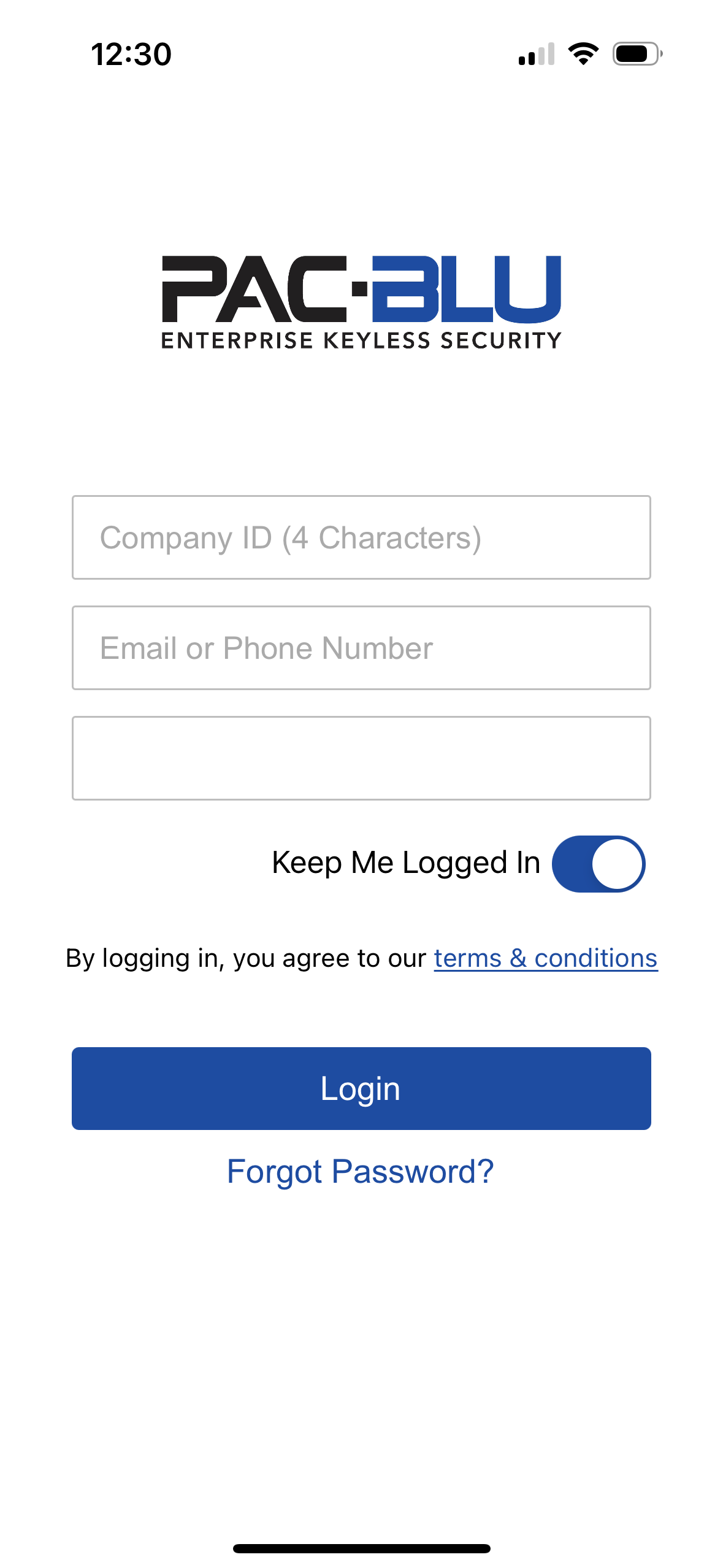
- Open the PAC-BLU NexGen app and log into your company account.
- Click below to download the app
- Tap the gear icon on the home screen to enter the device setup section.
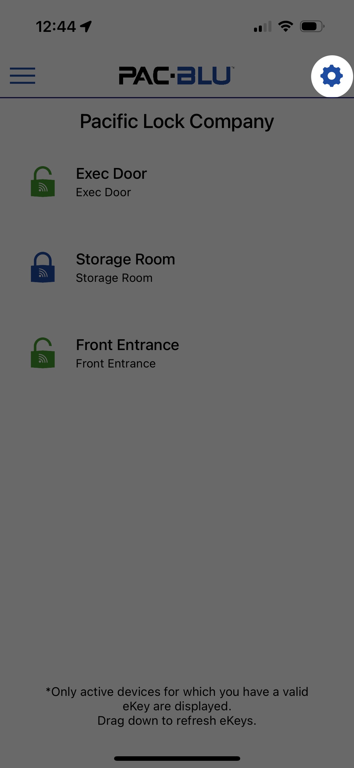
- On the Installer Screen, click “Add New” to setup the device.

- Select your corresponding serial number for your Access device.

- You will be prompted to update the device to ensure it has the latest software.
Configuring the Access
- Once updated, configure settings such as the device name, lock type, and other preferences.
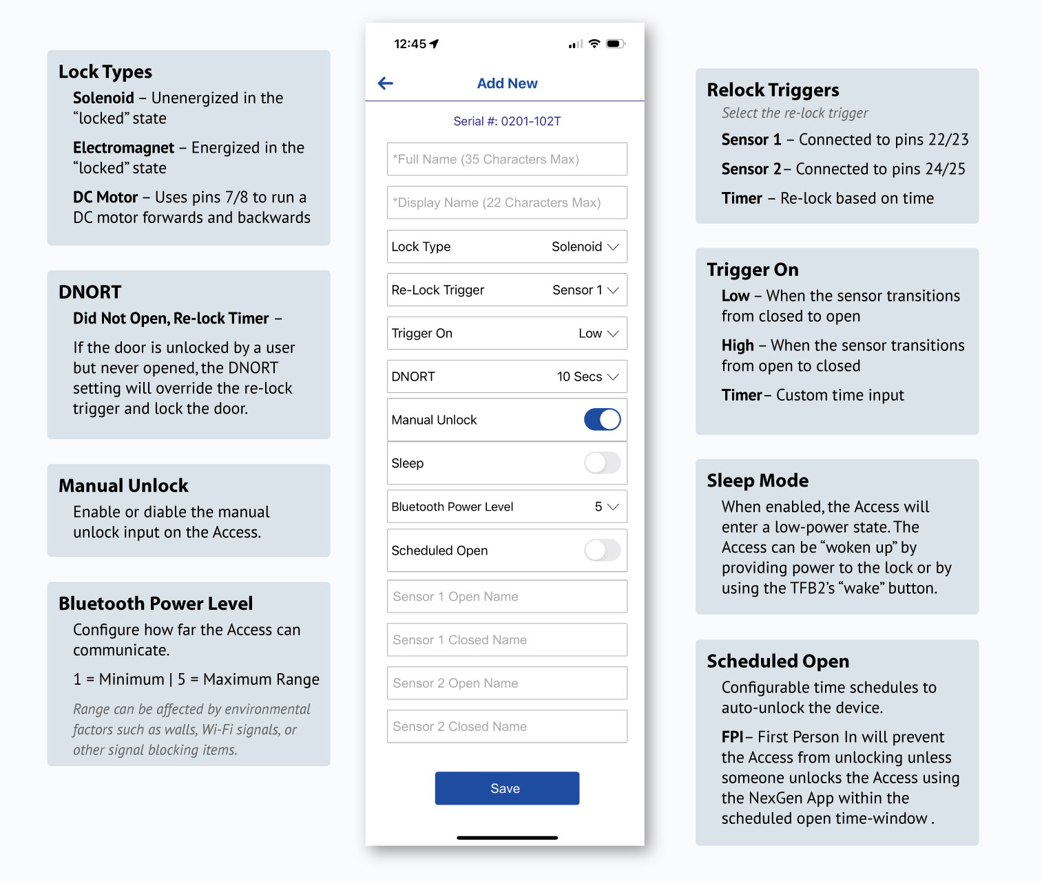
- Save your changes to complete the setup.
Important eKey Reminder!
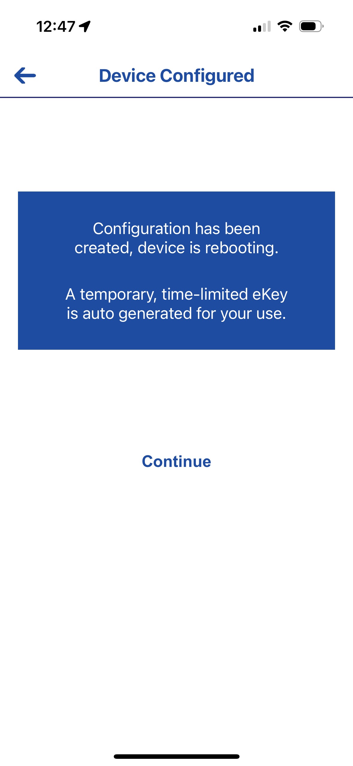
When a device is added, you’ll receive a temporary 2-hour eKey by default. Be sure to login to Sentinel and assign your self full access to ensure you don’t lose Access to the lock!
Adding Users and eKeys
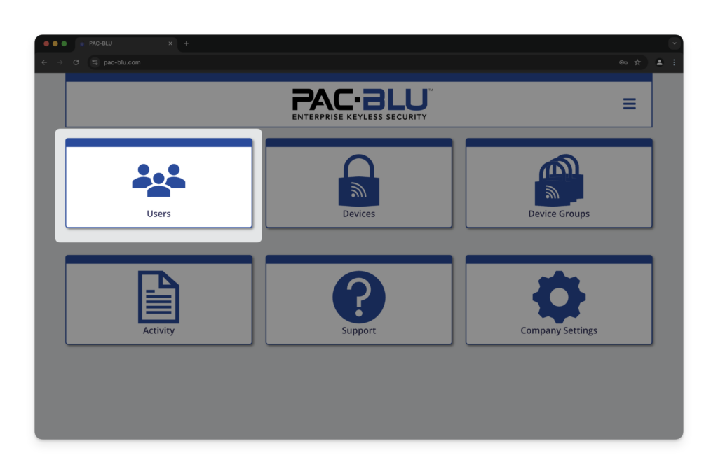
Adding a New User
Click the image below to view the “Adding a New User” post.
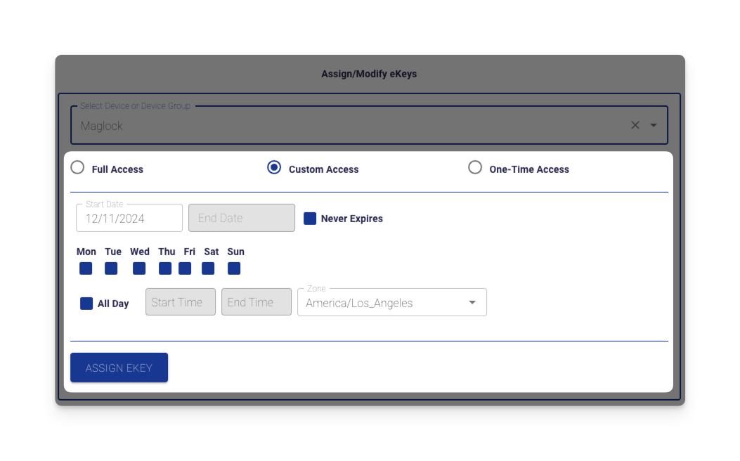
Assigning an eKey
Click the image below to view the “Assigning an eKey” post.
Thank You!
Thank you for choosing PACLOCK® and PAC-BLU™ for your access control needs. We are committed to providing innovative and secure solutions to protect your assets.
